Radar Cross Section (RCS)
What is RCS?
Radar Cross Section, or RCS, describes how strongly an object reflects radar energy back toward the radar receiver. It is represented by the symbol () and is measured in square meters .
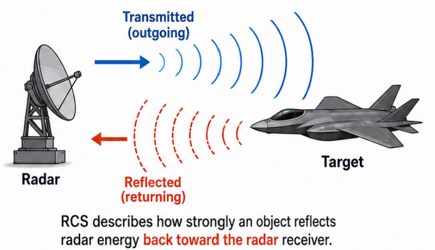
RCS should not be interpreted as the physical cross-sectional area of an object. Instead, it the effective area that describes how much radar energy a target redirects back toward the radar. An object with an RCS of produces the same received signal as a hypothetical isotropic reflector that collects radar energy over an effective area of and reradiates it uniformly in all directions.
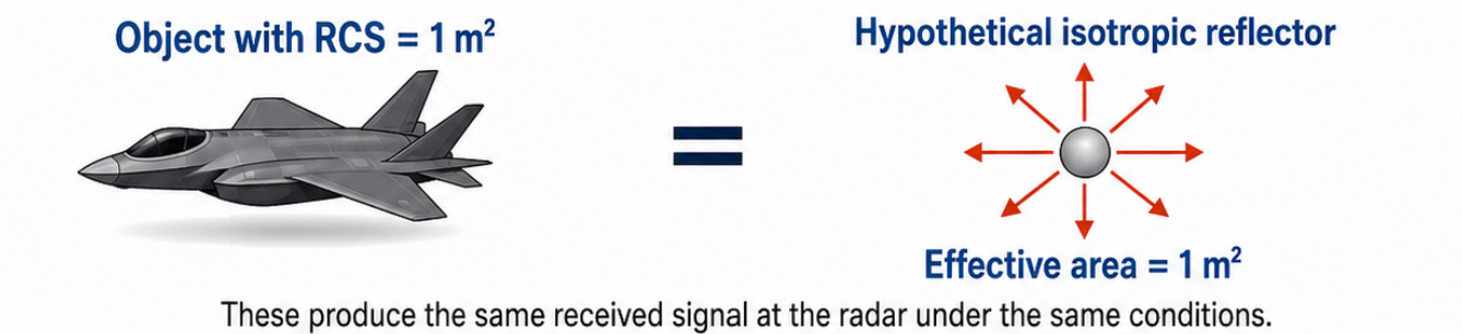
This means that a physically small object can have a large RCS if its geometry redirects energy efficiently toward the radar, while a much larger object may have a low RCS if most of the energy is reflected elsewhere.
What determines an object’s RCS?
The most important factors are material, size, shape, orientation, frequency and polarization.
| Factor | Usually increases RCS | Usually decreases RCS |
|---|---|---|
| Material | Conductive materials such as aluminum and steel | Plastics, foams and other weakly reflecting materials |
| Size | Larger illuminated area | Smaller objects or partially illuminated objects |
| Orientation | Large surface facing the radar | Edge-on or angled surface |
| Geometry | Corners, cavities and multiple reflecting surfaces | Smooth curves or slopes that redirect energy away |
| Frequency | Features that are large relative to the wavelength | Features that are very small relative to the wavelength |
| Polarization | Target geometry aligned with the radar polarization | Geometry poorly coupled to the transmitted polarization |
RCS is not normally one fixed value for an object. It can change significantly with the object’s orientation, radar frequency, polarization and viewing angle. Complex objects contain multiple reflecting surfaces whose returns can combine constructively or destructively, producing strong peaks and deep fades in the measured RCS.
This means that objects cannot always be ranked using simple rules such as “larger objects have higher RCS.” A small corner reflector may have a larger RCS than a much larger smooth or angled object.
A flashlight analogy may help: two objects can be the same physical size, but one may shine much more light back toward you because of its shape and orientation. RCS describes the strength of the radar “glint” seen by the sensor, not simply the object’s size.
Flat metal sheets
A flat sheet of metal can produce an extremely strong radar return when its broad surface is pointed directly toward the radar. In this position, much of the incoming energy reflects back toward the sensor.
However, a flat sheet is highly sensitive to alignment. When the sheet is tilted, it behaves somewhat like a mirror: most of the radar energy reflects away from the sensor instead of returning to it. A sheet viewed nearly edge-on can therefore produce a very weak return, even though it is made of metal.
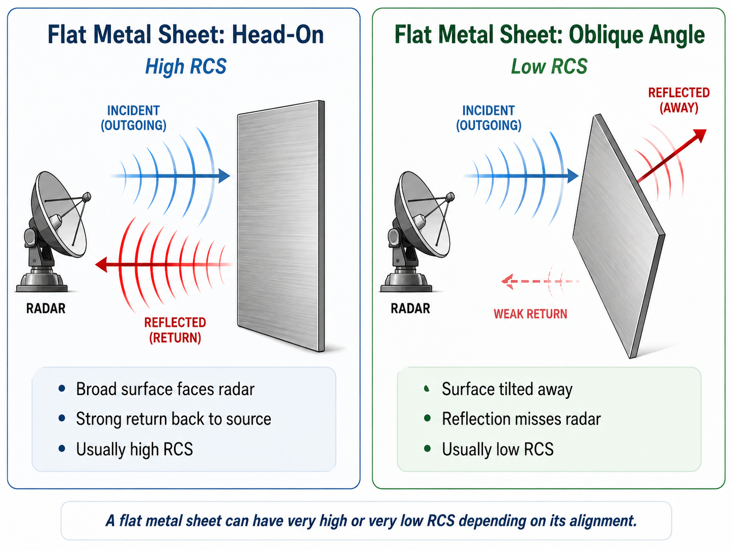
A flat sheet can consequently have either one of the highest or one of the lowest RCS values in this comparison, depending on its angle.
Corner reflectors
A trihedral corner reflector contains three metal surfaces that meet at right angles. Radar waves bounce between these surfaces and are redirected back toward the direction from which they arrived, giving it a strong RCS over a very wide variety of angular orientations.
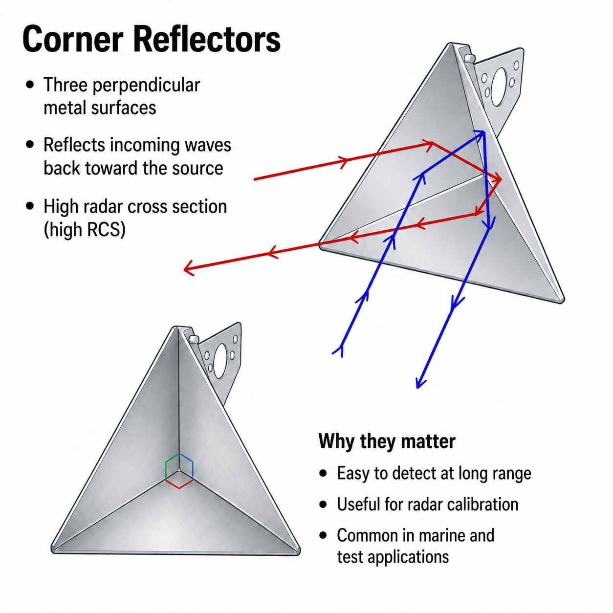
Corner reflectors normally produce a strong and predictable radar return over a wider range of viewing angles than a single flat sheet. This makes them useful for radar calibration, range testing, navigation markers, and marine safety.
A small corner reflector may produce a stronger return than a much larger object because its geometry is specifically designed to send energy back toward the radar.
Metal spheres
A metal sphere generally produces a weaker peak return than a well-aligned metal sheet or corner reflector of comparable size. Its main advantage is consistency.
Because a sphere looks the same from every direction, rotating it does not significantly change its radar return. This makes metal spheres useful as calibration references when engineers need a target with a known and repeatable response.
This also means that of the commonly used test shapes, it is most similar to the hypothetical ‘isotropic reflector’. The only difference is that a real metal sphere does not necessarily reradiate exactly the same amount of energy in all directions, so we still cannot assume that a sphere with surface area will have an RCS of as well.
Think of a metal sphere as a moderate but dependable reflector, while a flat sheet can be extremely strong or extremely weak, depending on its angle.
Cars
Cars often have relatively high RCS because they are large and contain many conductive components. Their body panels, frame, wheels, engine, and internal metal structures can all contribute to the radar return.
Cars also contain many edges, cavities, and corners that may redirect radar energy back toward the sensor. However, their RCS can change considerably as the vehicle turns because different surfaces become visible to the radar.
A car usually produces a much stronger return than a person or a nonmetallic chair, but it is less predictable than a purpose-built calibration reflector.
Chairs and other furniture
A metal chair can produce a noticeable radar return because of its metal legs, frame, joints, and right-angle structures. Its return will still vary depending on which parts face the radar.
A wooden or plastic chair normally produces a weaker return because these materials are less electrically conductive than metal. Metal screws, brackets, or support frames may still create small, strong reflections.
This means that two chairs of nearly identical size can appear very different to a radar if one has a steel frame and the other is mostly wood or plastic.
People
People generally have a lower RCS than cars and large metal objects, but they can still be detected by mmWave radar. The body contains water and other materials that reflect part of the transmitted signal.
A person’s RCS changes with posture, orientation, clothing, and movement. Someone facing the radar may produce a different return from someone standing sideways. Moving arms and legs also create changing reflections that can help the radar distinguish a person from stationary background objects.
People usually produce weaker returns than similarly sized metal targets, but often stronger and more complex returns than small wooden or plastic objects.
The most important comparison
The key difference is not simply metal versus nonmetal. It is how much energy the object sends back toward the radar:
- A face-on metal sheet can be extremely strong.
- The same sheet at an unfavorable angle can be extremely weak.
- A corner reflector is designed to return energy toward the radar.
- A metal sphere gives a stable return from almost every direction.
- Cars are usually strong but complicated and angle-dependent.
- People, wood, and plastic usually produce weaker returns, although their exact RCS still depends on size, shape, and orientation.
How to calculate RCS
The basic idea
Calculating RCS is similar to judging how reflective an object is by shining a flashlight at it and measuring how much light comes back.
A radar:
- Transmits a known amount of electromagnetic energy.
- That energy travels to the target.
- The target scatters the energy in many directions.
- A small portion returns to the radar.
- The radar measures the strength of that returning signal.
A stronger return generally means a larger RCS. However, the measured echo also depends on the target’s distance, the radar’s transmit power, the antennas, and losses in the system. These effects must be removed before the target’s RCS can be determined.
For instance, a weak received signal does not necessarily mean that the target has a low RCS—it may simply be far away. The RCS calculation corrects for this distance-related weakening.
The calculation must also account for how strong of a signal the radar transmitted, how directional its antennas are, and how much signal was lost in the hardware or environment.
Comparing the incoming and scattered fields
The formal definition of RCS compares:
- the electromagnetic field arriving at the target, and
- the electromagnetic field scattered away from the target in the direction being observed.
For a radar measuring the return back toward itself:
where:
- is the RCS in square meters,
- is the electric-field strength arriving at the target,
- is the scattered electric-field strength measured at the radar, and
- is the distance from the target to the measurement point.
The fraction
compares the strength of the scattered signal with the strength of the signal that illuminated the target. The electric-field values are squared because electromagnetic power is proportional to the square of the field strength.
The factor
corrects for the way the scattered energy spreads out as it travels away from the target. It represents the surface area of an imaginary sphere centered on the target.
Think of spraying water in every direction. As the water travels farther away, it becomes spread over a larger spherical area. A detector placed far away receives less water per square meter even though the original amount of water has not changed. Multiplying by removes this spreading effect.
Why does the equation use ?
The limit does not mean that the radar must literally be infinitely far away. It means the measurement should be made under far-field conditions.
Far enough from the target, the incoming radar wave behaves approximately like a flat, uniform wave across the target. This makes the RCS less dependent on the exact measurement distance and allows different measurements to be compared consistently.
At very short distances, different parts of a large object may receive noticeably different wave angles and strengths. In that case, the conventional far-field RCS definition may not accurately describe the measurement.
Calculating RCS from received radar power
In a practical monostatic radar like our mmWave, the transmitter and receiver are located together. RCS can then be related to the measured received power using the radar range equation:
This equation predicts how much power returns to the radar from a target with a particular RCS.
Rearranging it gives:
where:
- is the power received from the target,
- is the transmitted power,
- is the transmit-antenna gain,
- is the receive-antenna gain,
- is the radar wavelength,
- is the distance to the target, and
- represents system and propagation losses.
In simple terms, the radar begins with the measured power received, , and then corrects for the known radar settings, distance, antenna performance, wavelength, and losses.
Why does distance appear as ?
The radar signal makes a round trip:
- It spreads out while traveling from the radar to the target.
- The reflected signal spreads out again while traveling from the target back to the radar.
Each part of the trip introduces an approximate reduction in power density. Together, the two paths produce:
This is why radar echoes become weak very quickly as range increases.
For example, doubling the target distance reduces the received power to:
of its previous value, assuming everything else remains unchanged.
How RCS is determined in practice
For simple shapes such as metal spheres, flat plates, and corner reflectors, RCS can sometimes be calculated using established equations.
For complicated objects such as cars, drones, people, and machinery, RCS is usually found through:
- calibrated radar measurements,
- electromagnetic simulation, or
- comparison with a reference target whose RCS is already known.
A raw radar amplitude or range-FFT peak is not automatically an absolute RCS measurement. The radar must be calibrated so that antenna gain, receiver gain, processing gain, cable loss, background clutter, and other system effects are accounted for.
A reference target—often a metal sphere or corner reflector—provides a known return that can be used to convert measured radar amplitude into an estimated RCS.
Why does this matter in different applications?
RCS directly affects the received signal power and therefore the maximum distance at which a target can be detected. From the radar range equation:
For a fixed minimum detectable signal level:
Because of this fourth-root relationship, a large change in RCS produces a smaller—but still important—change in maximum range. For example:
- Reducing RCS to (10%) of its original value reduces maximum range to approximately (56%).
- Doubling RCS increases maximum range by only approximately (19%).
The practical importance of RCS depends on the application:
Autonomous navigation and automotive radar:
Vehicles and large metal structures generally produce strong returns, while pedestrians, animals, road debris and small nonmetallic objects may produce weaker or more variable returns. A radar’s maximum-range specification should therefore identify the assumed target RCS rather than providing one universal detection distance.
Drone and counter-UAS detection:
Small airframes may contain plastics, composites and thin metal components, and their apparent RCS can change rapidly as the drone turns. The detection range may therefore fluctuate even when the drone remains at approximately the same distance. Processing across multiple frames, frequencies or viewing angles can improve detection reliability.
Industrial sensing:
Metal machinery, containers and structural components often create strong returns. However, flat surfaces can behave specularly, meaning a small change in sensor or target angle can redirect the reflection away from the receiver. Sensor placement and alignment are therefore important.
Presence and occupancy sensing:
The return from a person must be separated from reflections produced by walls, floors, furniture and other surrounding objects. A high-RCS background object can create much more received power than the person being detected, making clutter removal and detection-threshold selection important.
Radar testing and calibration:
Known-RCS targets allow engineers to compare radar configurations, estimate system losses and verify detection range. They are also useful for confirming that measured amplitude remains consistent between different sensors or test setups.
Close-range note: Conventional RCS assumes that the complete target is illuminated under far-field conditions. At very short distances, the radar beam may illuminate only part of a large target. The measured effective RCS can therefore depend on range as well as the target itself.
RCS is consequently best treated as a target signature that varies with viewing conditions—not simply as a fixed number assigned to an object.